


Views: 104 Author: Site Editor Publish Time: 2026-08-13 Origin: Site


TFT LCD color depth defines how many color levels a display system can represent. It affects gradients, icons, photographs, medical graphics, camera images, dashboard appearance, and the amount of data that the processor must send to the display.
The terms RGB565, RGB666, and RGB888 describe how many bits are allocated to the red, green, and blue channels. They are often associated with 16-bit, 18-bit, and 24-bit color systems, but the final number of visible colors also depends on the panel driver, interface mapping, dithering or FRC, controller configuration, and the native capability of the LCD.
This guide explains the practical difference between RGB565, RGB666, and RGB888, why some TFT LCD datasheets list 262K or 16.7M colors, how color depth affects memory and bandwidth, and which format is suitable for industrial HMI, medical, automotive, embedded, and multimedia applications.
RGB565 / 16-bit: a practical choice for MCU-based HMIs, meters, handheld devices, and interfaces dominated by text, icons, gauges, and simple graphics.
RGB666 / 18-bit: useful when the panel or interface natively supports 6 bits per color channel and smoother color transitions are needed without the full data cost of 24-bit graphics.
RGB888 / 24-bit: preferred for photo-rich UI, camera feeds, medical visualization, automotive infotainment, high-end HMI, and applications where gradient quality matters.
Most important: the processor output format, LCD interface, driver IC, and panel color capability must match. A 24-bit framebuffer does not guarantee that the LCD itself is operating as a true 24-bit panel.
A color TFT LCD normally divides each pixel into red, green, and blue subpixels. The display controller changes the intensity of these subpixels, and the three components combine to create the perceived color.
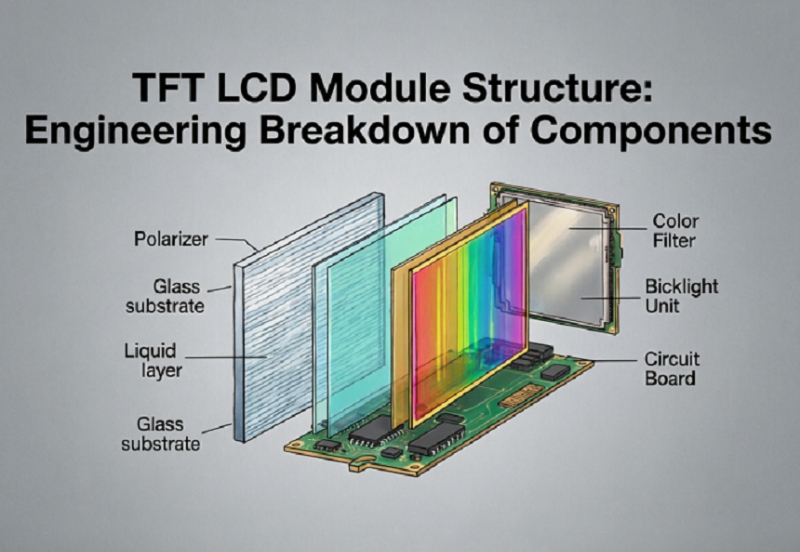
The TFT array controls the pixel state while the RGB color filter produces red, green, and blue subpixels.
The color-filter layer and driver electronics are therefore central to color-depth performance. For a full structural explanation, read TFT LCD Module Structure: Engineering Breakdown of Components.
Format | Bits per Pixel | Channel Allocation | Nominal Color Count | Typical Use |
|---|---|---|---|---|
RGB565 | 16 bit | 5R + 6G + 5B | 65,536 | MCU HMI, instruments, embedded UI |
RGB666 | 18 bit | 6R + 6G + 6B | 262,144 | Industrial panels with 6-bit-per-channel driver |
RGB888 | 24 bit | 8R + 8G + 8B | 16,777,216 | Photo, video, medical, automotive, premium HMI |
The nominal mathematical color count describes the digital format. The actual panel may use native 6-bit, 8-bit, or 6-bit plus FRC processing, so always check the LCD datasheet and driver configuration.
RGB565 is a 16-bit color format. Five bits are assigned to red, six to green, and five to blue.
Green receives one extra bit because the human visual system is particularly sensitive to variations in green luminance. This allocation gives better visual efficiency than dividing 16 bits equally across the three channels.
Lower framebuffer memory requirement
Lower memory bandwidth
Lower interface traffic
Good support in MCUs and embedded graphics libraries
Enough color for many gauges, icons, text, and machine-control screens
For a basic HMI, RGB565 can provide a clean and responsive interface without forcing the processor to move 24 bits for every pixel.
The lower number of color levels can become visible in smooth gradients, shadows, photographs, skin tones, and large areas that transition gradually from one shade to another.
This effect is commonly called color banding.
RGB666 uses six bits for each red, green, and blue channel, creating an 18-bit pixel format with 262,144 nominal color combinations.
Many industrial TFT panels and driver ICs use 6-bit-per-channel color internally. Some datasheets therefore list approximately 262K colors.
RGB666 provides smoother gradients than RGB565 while using less data than a full 24-bit RGB888 path.
Industrial HMI with more detailed graphics
Panels whose native driver is 6-bit RGB
Embedded Linux systems
LVDS panels with 6-bit color mapping
Applications where 16-bit banding is visible but full 24-bit color is unnecessary
RGB888 uses eight bits for each channel, giving 24 bits per pixel and approximately 16.7 million possible digital color combinations.
This format is common in modern graphics processors, Android systems, X86 systems, video pipelines, camera interfaces, and higher-end industrial displays.
Smoother gradients
Better photo reproduction
Reduced visible color banding
Better suitability for camera and video content
More flexibility for modern UI design
The 3.5-inch Toroson industrial TFT product page, for example, lists a 54-pin RGB interface and 16.7M colors, showing that compact embedded panels can also support full-color graphical applications.
Likewise, Toroson's 7-inch 1200×1920 MIPI module is specified for up to 16.7M colors, which is more appropriate for image-rich interfaces and higher-resolution GUI designs.
7-inch high-resolution MIPI TFT LCD — an example of a panel designed for image-rich embedded interfaces.
Color Class | Digital Format Direction | Visual Strength | Main Risk |
|---|---|---|---|
65K | 16-bit RGB565 | Efficient for UI, icons and gauges | Visible banding in smooth gradients |
262K | 18-bit RGB666 | Better gradient smoothness | Still fewer native levels than true 8-bit/channel |
16.7M | 24-bit RGB888 direction | Strong photo/video and gradient quality | Higher memory and bandwidth demand |
Some industrial TFT LCD datasheets list two color numbers such as 256K / 16.7M. This often indicates that the panel can operate with different color-depth or dithering/FRC configurations depending on the driver and input mapping.
For example, lcdsell.com lists both 256K and 16.7M color capability for its 12.1-inch 1024×768 IPS LVDS module.
That is why color count should never be separated from:
LVDS bit mapping
Driver IC capability
FRC or dithering support
Controller output format
Panel initialization and timing
If you are reviewing a specific model, use the TFT LCD Datasheet Guide to verify color depth together with interface, timing, voltage, backlight, temperature, and mechanical dimensions.
FRC stands for Frame Rate Control. It alternates nearby color values across time so the human eye perceives an intermediate shade.
A 6-bit-per-channel panel provides 64 native levels for each color channel. With temporal processing such as FRC, the display can approximate additional intermediate levels and present smoother gradients.
Procurement note: “16.7M colors” does not always mean native 8-bit-per-channel LCD glass. If true native color depth matters for medical, imaging, calibration, or color-critical equipment, ask whether the panel is native 8-bit or 6-bit + FRC.
Color banding appears when a smooth gradient is displayed with too few intermediate levels. Instead of a continuous transition, the user sees visible steps or bands.
Banding is most noticeable in:
Gray gradients
Sky or shadow images
Medical heat maps
Camera feeds
Dark-theme backgrounds
Large soft-color UI areas
Banding can come from more than the LCD itself. Possible causes include:
16-bit framebuffer output
Image compression
Incorrect LVDS mapping
Driver configuration
Panel native color depth
Software rendering pipeline
Color depth describes the number of digital levels available. Color gamut describes the range of colors the display can physically reproduce.
A panel can support 16.7M digital colors but still have a modest NTSC or sRGB gamut. Likewise, a wide-gamut panel still requires sufficient bit depth to render gradients smoothly.
Specification | What It Measures |
|---|---|
Color depth | Number of available digital color levels |
Color gamut | Range of reproducible colors |
Color accuracy | How closely displayed colors match the target values |
Resolution determines how many pixels must be drawn. Color depth determines how many bits are required for each pixel.
Increasing both at the same time can multiply the memory and bandwidth requirement.
Resolution | RGB565 Framebuffer | RGB888 Framebuffer |
|---|---|---|
800×480 | Approx. 0.73 MiB | Approx. 1.10 MiB |
1024×600 | Approx. 1.17 MiB | Approx. 1.76 MiB |
1280×800 | Approx. 1.95 MiB | Approx. 2.93 MiB |
1920×1080 | Approx. 3.96 MiB | Approx. 5.93 MiB |
These values are for a single raw framebuffer and do not include double buffering, alpha channels, overlays, compression, or system memory overhead.
For resolution-level planning, read the TFT LCD Resolution Guide.
More bits per pixel require more data transmission unless compression or serial encoding changes the physical link behavior.
The interface should therefore be evaluated together with:
Resolution
Refresh rate
Bits per pixel
Lane or channel count
Pixel clock
Controller output capability
A parallel RGB interface may expose individual color-data lines directly. An RGB888 implementation can require 24 color-data signals before clock, sync, DE, and control lines are counted.
LVDS serializes pixel data. Industrial LCDs may use 6-bit or 8-bit LVDS mappings, and the controller must use the correct JEIDA/VESA mapping when applicable.
MIPI DSI carries pixel data over high-speed serial lanes. It is common in compact high-resolution modules where a wide parallel RGB bus would be inconvenient.
For interface-level selection, see LCD Interface Selection Guide: RGB vs LVDS vs MIPI.
Wide viewing angle and color stability often matter together. The Toroson 10.1-inch 800×1280 MIPI IPS module is an example of a compact display intended for modern embedded graphics and touch-oriented interfaces.
10.1-inch MIPI IPS TFT LCD — suitable for high-resolution graphical interfaces where viewing stability and color presentation matter.
Panel mode does not define color depth by itself. If you also need to compare viewing behavior, read IPS vs TN TFT LCD for Industrial Applications.
For a microcontroller, RGB565 is often attractive because memory and bandwidth are limited.
Choose RGB565 when:
The UI is mostly text, icons, gauges, and flat-color graphics.
The processor has limited external memory bandwidth.
Fast drawing speed matters more than photo-quality gradients.
The LCD or graphics library is already optimized for 16-bit pixels.
Consider RGB888 when:
The MCU or MPU has sufficient external SDRAM/DDR.
The display shows photographs or camera content.
Banding is unacceptable.
The graphics accelerator is designed for 24-bit or 32-bit surfaces.
Android and X86 platforms normally have much greater graphics and memory capability than small MCUs. For these systems, 24-bit color or a 32-bit framebuffer format is common.
The remaining questions become:
Does the LCD accept the same effective color depth?
Is the LVDS/eDP/MIPI mapping correct?
Does the controller introduce dithering?
Does the panel use native 8-bit or 6-bit + FRC?
Does the complete UI need color calibration?
If the display is connected through a dedicated board, the LCD Controller Board Selection Guide can help separate panel requirements from platform requirements.
Application | Practical Direction | Why |
|---|---|---|
Basic machine HMI | RGB565 often sufficient | Efficient for icons, text and status graphics |
Handheld instrument | RGB565 / RGB666 | Balances visual quality, memory and power |
Medical visualization | RGB888 direction | Smooth gradients and image detail may be more important |
Camera monitor | RGB888 direction | Reduces visible banding in natural images |
Automotive infotainment | RGB888 direction | Photo, map, animation and video-rich UI |
Industrial monitoring dashboard | RGB666 / RGB888 | Better smoothness for charts and dark-theme gradients |
Some displays use 6-bit + FRC to approximate additional colors.
Better approach: Ask for the native panel bit depth and FRC information.
The GUI looks better on paper, but the MCU cannot maintain the required framebuffer or redraw rate.
Better approach: Calculate memory and bandwidth before locking the pixel format.
A 24-bit digital pipeline is assumed to guarantee wide-gamut color.
Better approach: Check color depth, gamut, color accuracy, and panel mode separately.
The panel displays incorrect colors even though the interface is electrically connected.
Better approach: Verify 6-bit/8-bit mapping, JEIDA/VESA configuration, lane mapping, and controller firmware.
The root cause is actually a 16-bit framebuffer, compressed image, or software rendering path.
Better approach: Test the entire graphics pipeline from source image to LCD output.
A higher color depth is selected without accounting for the additional data load at the target resolution and frame rate.
Better approach: Review resolution, color depth, refresh rate, interface bandwidth, and controller together.
Screen size: required diagonal size
Resolution: native pixel format
Required color depth: RGB565, RGB666, RGB888, or panel-native format
Color number: 65K, 262K, 16.7M, or other target
Native panel bit depth: 6-bit, 8-bit, 6-bit + FRC
Interface: RGB, LVDS, MIPI DSI, eDP
Controller platform: MCU, FPGA, MPU, Android, X86
Memory limit: internal RAM / external SDRAM / DDR
Content: text, icons, gradients, photos, camera, video
Viewing angle: TN or IPS requirement
Brightness: indoor or high-brightness target
Operating temperature: minimum and maximum
Touch: PCAP, resistive, or no touch
Annual quantity: prototype and production demand
RGB565 uses 16 bits per pixel and provides 65,536 nominal colors. RGB888 uses 24 bits per pixel and provides about 16.7 million nominal colors, giving smoother gradients but requiring more memory and bandwidth.
Green is allocated six bits while red and blue receive five because the human visual system is particularly sensitive to green luminance differences.
RGB666 has 18 bits per pixel, giving 262,144 nominal color combinations.
No. Some panels use native 6-bit color plus FRC or dithering to approximate additional color levels.
Yes for many HMIs dominated by text, icons, gauges, and flat-color graphics. Applications with photographs, camera feeds, medical images, or smooth gradients may benefit from greater color depth.
No. Resolution and color depth are separate. RGB888 gives more color levels per pixel but does not increase the number of pixels.
Banding can come from low bit depth, image compression, panel limitations, FRC behavior, incorrect interface mapping, or the software graphics pipeline.
Often yes, but the data must be mapped correctly and the controller may need to discard or dither the least significant bits. The exact connection depends on the panel interface and timing specification.
No. MIPI is an interface technology. The pixel format and panel-native color depth must still be verified separately.
Provide the size, resolution, interface, controller platform, color-depth requirement, image-content type, viewing angle, brightness, temperature range, touch requirement, and expected quantity.
RGB565, RGB666, and RGB888 should be selected according to the complete display system rather than by choosing the largest color number.
For compact MCU-based HMIs, RGB565 can reduce memory and bandwidth while still producing clear industrial graphics. RGB666 is useful when the LCD or LVDS path is natively 6-bit per color channel. RGB888 is the stronger choice when smooth gradients, photos, medical graphics, maps, camera feeds, or premium UI quality are required.
Before finalizing a TFT LCD, confirm the panel’s native bit depth, FRC support, interface mapping, controller output format, resolution, refresh rate, memory bandwidth, color gamut, and real application content.
Send the display size, resolution, RGB565/RGB666/RGB888 requirement, controller platform, interface type, content type, brightness, temperature range, touch requirement, and expected quantity. Toroson can help compare TFT LCD panels and verify color-depth, interface, and controller compatibility for your OEM project.


